Back to 3 Foot 6 Axis Robot ArmMechatronics

Solo project

Cycloidal Gearboxes

The actuator transmission for the Six-DOF arm. Development started with a standard single-stage cycloidal gearbox, then branched into a custom three-ring cycloidal drive (inspired by Mishin Machine) chasing extremely backdrivable, low-backlash motion. This sub-project tracks both lines of work and the iterations behind them.

Project Summary

What I built

A short look at the build, the main technical choices, and the pieces I iterated along the way.

Overview

The gearboxes are the actuator transmission for the Six-DOF arm. I started with a standard single-stage cycloidal drive, got it running and load-tested, then branched into an experimental three-ring cycloidal drive to chase better backdrivability.

What I Built

A working 20:1 standard cycloidal actuator, and a five-revision three-ring cycloidal drive prototyped from hand-crank rigs up through motorized load tests.

Technical Highlights

The standard drive stalls at 50 percent of theoretical capacity for a 20:1 ratio on a NEMA 17. The three-ring line surfaced slipping plates and inner-pin bending, and after fixes still showed low torque efficiency, so the production actuator went back to the standard layout.
Drives

Gearbox in progress: Innie Cycloidal

The current gearbox in progress is the innie cycloidal drive, shown first. Everything below it is past iteration work that led here — the earlier outie cycloidal, then the experimental three-ring cycloidal drive.

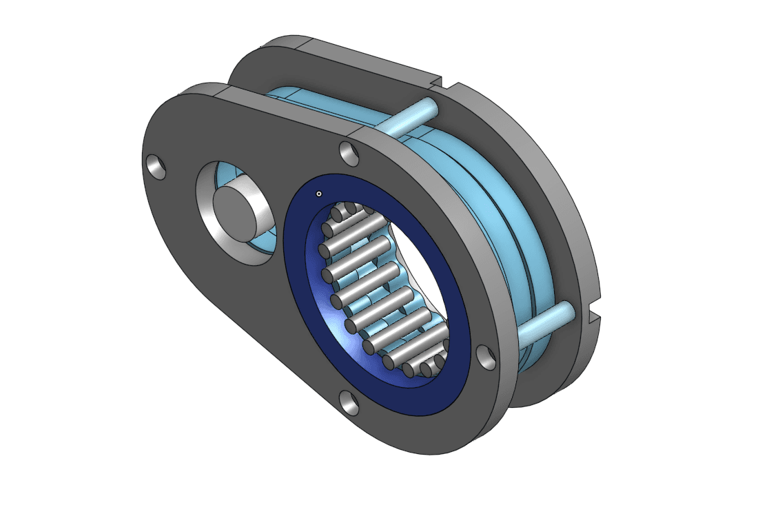
"Innie" Cycloidal Drive (in progress)

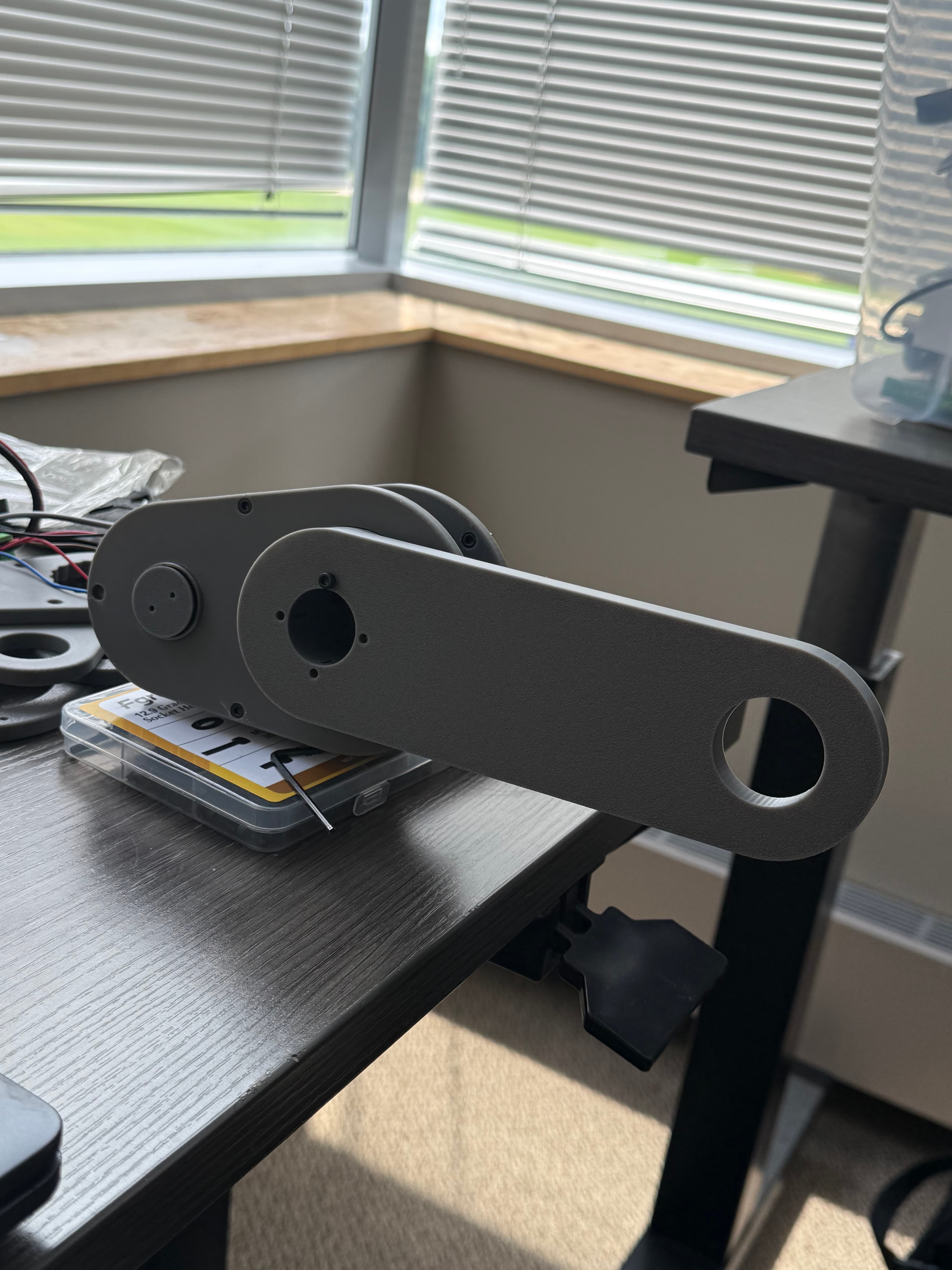
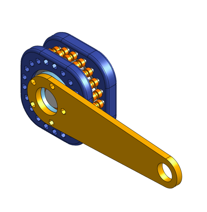
The current gearbox in progress. A single-stage 20:1 cycloidal actuator driven by a NEMA 17, redesigned with the output rollers pulled inside the housing for a more compact, better-supported drive than the earlier outie layout.

  • Redesigned from the earlier "outie" cycloidal into the current "innie" layout, moving the output rollers inboard for a tighter, better-supported package.
  • Aimed at improving the torque efficiency measured on the earlier drives before committing it to the arm.
"Innie" Cycloidal — CAD
image

"Innie" Cycloidal — CAD

The current innie cycloidal design, with the output rollers pulled inboard between the plates and the output crank arm on the front.

video

"Innie" Cycloidal — Assembled Hardware

The assembled innie drive with the cap off, showing the ring of inboard rollers and the output arm seated on them.

Past iterations

Everything below is earlier gearbox work that led to the current innie drive — the designs it replaced, kept here as the iteration history. First the outie cycloidal it grew out of, then the experimental three-ring cycloidal drive.

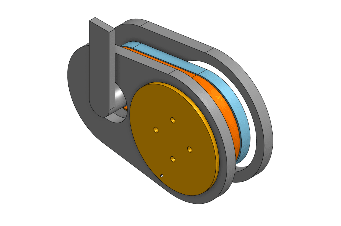
"Outie" Cycloidal Drive (past iteration)

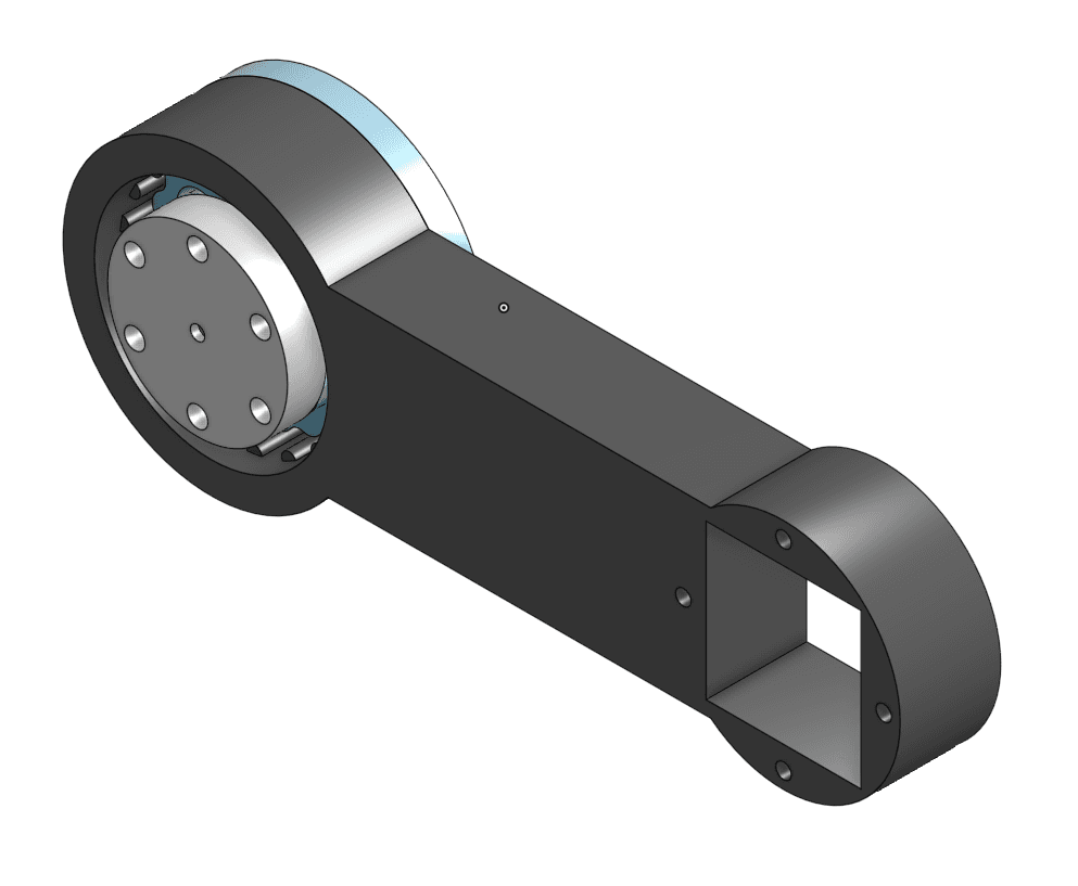
The earlier cycloidal layout, with the output link and square drive socket. This is the design the innie cycloidal replaced.

  • First working cycloidal actuator layout, with the output rollers on the outer face.
  • Surfaced the early backlash and packaging issues that drove the move to the innie redesign.
"Outie" Cycloidal — CAD
image

"Outie" Cycloidal — CAD

The earlier outie layout, with the output link and square drive socket.

video

Initial Backlash Problems

video

Motion Demo

video

Inside Cycloidal View

video

Stall Under Load

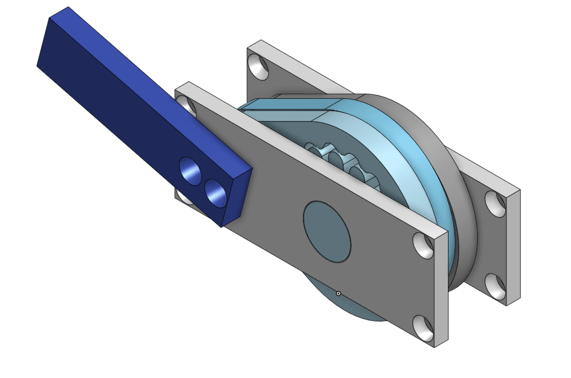
Three-Ring Cycloidal Drive (past iteration)

A custom three-ring cycloidal drive inspired by Mishin Machine, aimed at extremely backdrivable, low-backlash motion. Five hardware revisions, each hand-cranked before motorizing to check smoothness before load testing.

  • Prototyped v1–v5, hand-cranking each revision to feel out smoothness and backdrivability before motorizing.
  • Fought slipping stacked plates and inner-pin bending across v2–v4 with metal pins, more plate spacing, and flanged bearings on every shaft.
  • Measured low torque efficiency on v5 after all fixes, and used that result to switch the production actuator back to the standard cycloidal layout.
v1 — Hand-Crank Test
image

v1 — Hand-Crank Test

First three-ring concept in Onshape, set up as a hand-cranked rig to feel out smoothness and backdrivability before motorizing.

v2 — Metal Pins
image

v2 — Metal Pins

Swapped in metal pins to survive load, still hand-cranked for evaluation.

v3 — Slipping Plates
image

v3 — Slipping Plates

Stacked plates slipped against each other under load, making torque measurements unreliable.

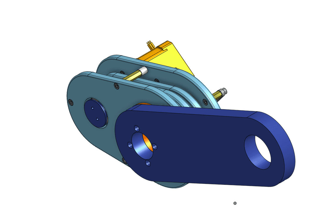
v4 — Motor Test, Inner Pin Bending
image

v4 — Motor Test, Inner Pin Bending

First motorized test surfaced inner-pin bending under torque.

v4 — Full Assembly, Real-Life View
image

v4 — Full Assembly, Real-Life View

The fully assembled v4 three-ring drive.

video

v4 — Hand-Crank Backdrive (No Output Arm)

Hand-cranking the v4 drive with no output arm attached to check smoothness and backdrivability.

video

v4 — Backdrive Demo (With Output Arm)

The motorized v4 hardware with the output arm attached, showing the smooth, highly backdrivable motion the three-ring layout was chasing.

video

v4 — Plate Shifting Demo

The stacked plates shifted relative to each other under torque, degrading the transmission.

video

v4 — Inside Pin Slipping Demo

Under load the pins slipped, one of the failure modes that showed up once v4 was driven by the motor.

v5 — Final Test
image

v5 — Final Test

After all fixes the drive still showed low torque efficiency, so I switched the production actuator back to the innie cycloidal layout.